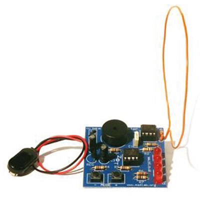
I found a great beginner’s project, the MadLab Junior Theremin, as a cheap electronics kit available on Jameco!
Build and Demo Video
Here’s a video from Youtuber 3DSage that shows off a nice build tutorial along with the functionality of the Junior Theremin:
Theremins are extremely cool to play around with, but are bulky and a bit expensive. The MadLab Junior Theremin is a stripped-down version of the famous proximity-controlled instrument. One key difference is the lack of a volume control antenna, but the pitch control aerial/antenna is way more interesting! Simply move your hand closer to the antenna and listen to how the pitch changes.
Another difference is the introduction of software control via a 12C508 PIC microcontroller. MadLab offers their source code for the more adventurous DIYer out there to expand upon their program. If you’re looking to expand your electronics skills, this is a great way to get there! Be aware that you will probably need to find or purchase a compatible PIC programmer (see the 12C508 datasheet for compatible and recommended programmers).
Schematic Review
The circuit’s schematic is really easy to understand, so it’s also a cool teaching tool for basic electronics application.
5V Regulator
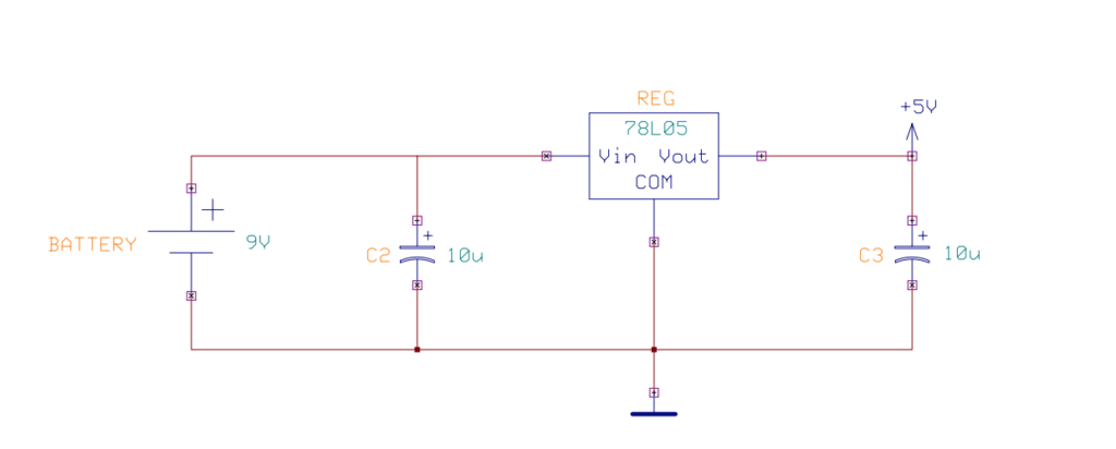
The circuit is powered by a 9V battery that is fed into a regulator to supply 5V to the schematic’s ICs. 9V batteries tend to be expensive, so I recommend learning how to create your own power supply so you can use an AC adapter.
555 Astable Multivibrator with Antenna Capacitance

This circuit block should be very familiar to those of us out there who have tackled the Atari Punk Console circuit or made an LED blink with a 555 timer IC. The only key difference is that AERIAL antenna replaces a capacitor in this traditional circuit. Resistors R1 and R2 combined with the AERIAL (just a wire) determine the square wave oscillation frequency.
For more information about this circuit, check out this page for calculations, theory, and more!
Microcontroller with Piezo Audio Output

This circuit is impossible to explain without referring to the source code that is programmed onto the 12C508 PIC microcontroller.
Without going into too much detail or saying something incorrect (I am no PIC programmer), the clock pulse signal that is generated by the 555 astable multivibrator + aerial circuit is fed into the PIC at GP2. The two switches change the PIC’s state from continuous to discrete mode. LEDs flash based off of internal state in coordination with the output frequency. The piezo outputs a pleasing tone in discrete mode, and an atonal pitch in continuous mode. Pushing the switches together changes mode. All of these actions can be deduced from the published source code!
Customization
There’s so much room for us DIYers to take this circuit and make it our own! Here are some ideas:
- Remove the piezo and replace it with an audio jack or pipe the output to amplifier circuit.
- Convert the circuit to use an Arduino. It might take a few hours to rewrite the source and convert the circuit, but you will gain experience with microcontrollers and build your own unique circuits.
- Mess around with the switch inputs (GP0 and GP1 in the schematic above)!
Until next time, happy hacking!


How do I get the program for this IC?
I don’t want to buy another kit. I just want to reprogram the IC. It seems like a shock wave to the IC scrambles some of the data on the IC. It doesn’t sound and function the same anymore after I dropped it.
How would u go about changing the sensitivity of the Ariel, I’m wanting more sensitive so would trigger from a foot away instead of few inches